|
|
 CHAPTER 24, Inc., MADISON, WI |
- Home
- Meetings
Schedule - Meeting
Minutes - Chapter
By Laws - Chapter
Officers -
Technical
Documents -
EAS
Info -
Chapter
Archives - Sustaining
Members -
Broadcasters
Clinic - DTV for
Consumers - Links
GEOSTATIONARY ORBITS PART 4: by Neal McLain, CSBE |
 |
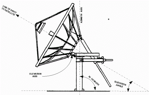
| 4.5-meter satellite antenna on EL/AZ mount (Andrew Corporation). |
Note that:
• Elevation is adjusted by rotating the antenna about the elevation axis. The elevation axis is always horizontal; rotation of the antenna about this axis moves the antenna beam along a vertical line.
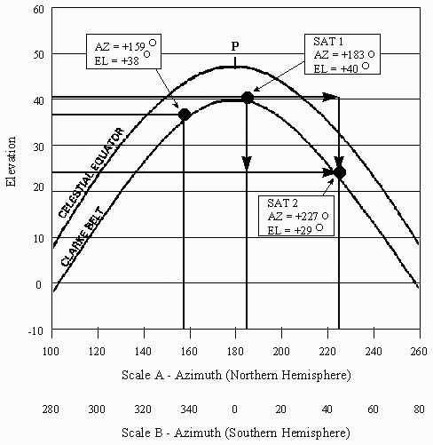
An EL/AZ-mounted antenna is relatively difficult to adjust if it must be moved from one geostationary satellite to another, because both azimuth and elevation must be adjusted. This difficulty is illustrated in the following figure. Note that moving an antenna from one satellite to another requires two motions, one along each axis. For example, to move from SAT1 to SAT2, the antenna must be moved to the right, and also moved down.
 |
Azimuth and elevation are EL/AZ mounts are used in many other fields as well; for several examples, click here.
POLAR MOUNTS
The second type of mount is called a polar mount, sometimes called an equatorial mount.
Compared with an EL/AZ mount, a polar mount is more complicated to construct and install.
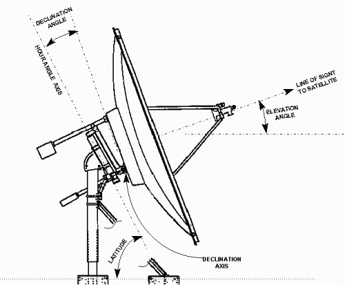
The geometry of a polar mount is illustrated in the following figure:
 |
| 3.8-meter satellite antenna on polar mount (Comtech Antenna Systems, Inc.). |
For proper operation, a polar-mounted antenna must be carefully aligned with respect to the earth's polar axis.
Note that:
• Declination is adjusted by rotating the antenna about the declination axis. The declination axis is always perpendicular to the hour angle axis (and hence, parallel to the equatorial plane); rotation of the antenna about this axis moves the antenna beam along a line which is perpendicular to the Celestial Equator.
• The angle between the hour angle axis and the earth's surface equals local latitude.
• At hour angle 0° (antenna aimed straight north or south), declination is related to satellite elevation and local latitude as follows:
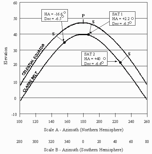
A polar-mounted antenna is relatively easy to adjust if it must be moved from one geostationary satellite to another, because only hour angle must be adjusted. This is illustrated in the following figure:
 |
Here we see the great advantage of a polar mount over an EL/AZ mount: once the declination angle is set to the correct value, the antenna tracks the Clarke Belt with very little error. As a result, the antenna can be moved from one geostationary satellite to another simply by moving just one axis: hour angle. Note, as an example, the move from SAT1 to SAT2: in this case, the declination angle error is only 0.1°.
Because of this fact, many polar-mount antennas are constructed with fixed declination adjustments: declination is set when the antenna is installed, and locked in place.
Nonetheless, some slight declination error does exist. This error may be significant in the case of high-gain antennas with very narrow beamwidths, particularly at Ku band. These antennas are sometimes fitted with mechanisms which adjust declination over a small angle, typically about ±1° from the average declination value.
The concept of the polar mount was borrowed from the field of astronomy, where it has been used for centuries. For several examples, click here.
CLASSIFICATION BY CONTROL METHOD
Antenna mounts also can be classified by control method, as fixed or steerable:
• A steerable mount is equipped some sort of mechanism which moves the antenna from one satellite to another. Electric motors are most common, although some mounts employ hydraulic mechanisms. Most steerable mounts can be controlled from a remote location by a device called an antenna controller. Controllers vary from simple switches to computerized systems which can store multiple satellite positions and operate automatically on a pre-determined schedule.
PUTTING IT ALL TOGETHER
If we combine these classifications, we obtain four possible mount configurations:
• FIXED EL/AZ
• STEERABLE EL/AZ
• FIXED POLAR
• STEERABLE POLAR
As a practical matter:
• Small steerable antennas are almost always polar-mounted. If the antenna aperture is less than about 4 meters and the antenna must be moved frequently, use of a polar mount greatly simplifies the process: only the hour angle axis must be motorized. The antenna can be moved through the entire visible portion of the Clarke Belt by changing only the hour angle. Virtually all C-Band "backyard dishes" employ polar mounts.
• Larger steerable antennas may be either EL/AZ- or polar-mounted. Some manufacturers prefer EL/AZ mounts; others prefer polar mounts. The single-axis simplicity of the polar mount makes these antennas easier to adjust; however, the necessity for declination-error correction partially negates this simplicity.
The type of mount used in any particular situation is, of course, dictated by the application. Fixed antennas are generally used only in situations where they are not moved frequently; for example, network-feed downlinks at broadcasting and cable television facilities. In most other applications, steerable antennas are required.
Orbits Index Page